Radio Platform Vehicles
Additional Information
This is where information for all radios beyond the simple mass produced RT series of radios lies. So this page does not cover the RT 66, 67, 68 series in the early M151 and the RT 524 / 246 & PRC-77 series from the mid 1960 to the late 1980s when the M151 series was being phased out.
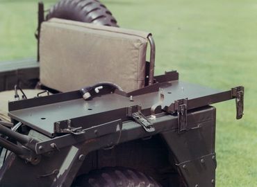
Many of these M151s would of had 100 amp charging systems installed. Pictures of this will be updated soon. What is a "sponson" mount. This is the specific adapter bracket between the vehicle (and its specific shape or ???) and the mount (specifically made for the radio) that the radio or radio assy sits in.
All Collins Factory photos from reference library, and were captioned by the late Dave Ross. Thanks go to Brian Bjerkelund, k7ais, for allowing us to present this information.
Some of the Radio Sets covered in the section below:
AN/GRC-19 Radio Set
TLQ-17A Radio Set
AN/GRC-106 Radio Set
AN/VRC-80 Radio Set
AN/VRC-81 Radio Set
AN/PRC-47 Radio Set
AN/MRC-83
Radio set, Vehicular, Mounted on a M-151 jeep, 2-30 MHz, 1 KW, AM, SSB, CW, Consists of R-761, T-730, C-3341, CU-749, C-2848, AM-2306 and CV-786, Collins Radio
AN/MRC-107 & 108
AN/MRC-109 & 110
AN/MRC-119 & 120 (AN/MRC-85)
AN/MRC-138
AN/PRD-1 Direction Finder Set
PRC-105, PRC-515, VC-120 & other ManPack or....Non-standard Radio Sets Jeep mounted
AN/URC-40

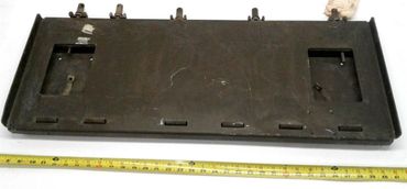
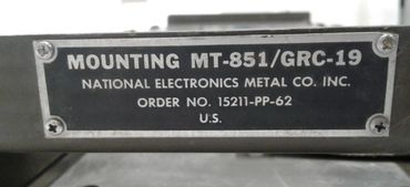
AN/GRC-19 Radio Set
Angry 19 - I have yet to find pictures or manuals for this set that pertain to the M151. I do have a picture of this mounted with the AN/PDR-1 Direction Finder. Butt it is split onto 2 mounts.

AN/GRC-19 Radio Set Details
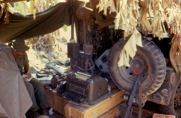
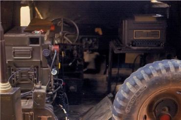
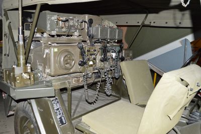
AN/MRC-83 Radio Set
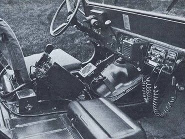
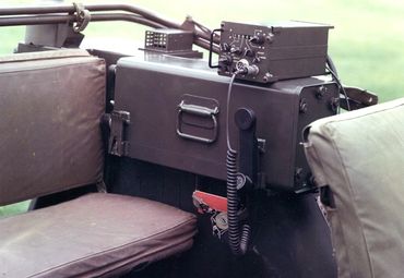
This picture to the right is in an M38A1 but would have been the same set up in an M151. Publicity photo of a complete MRC-83 radio set, a TRC-75 installed in an M38A1 jeep. Visible underneath the radio is the power supply box carrying the PP-2352 inverter - the inverter runs off 28VDC and makes 115 VAC 400~ 3 phase power for the radio. On the front of the power supply box are controls for the inverter and also a rudimentary selftest setup for the inverter with lamps to give a go-nogo indication as to the health of each chopper transistor in the inverter. The MRC-83 first saw the light of day around 1960 - in those days it was quite a feat to put a 1kW automatically-tuned HF radio in a vehicle. I saw over 2000 TRC-75 radio sets come up for disposal at DRMO Barstow in the early 1990s, and I guess that most of those radios were installed in M38A1 jeeps just like this one - the 1960s was an excellent time to own stock in the Collins Radio Corporation. Credit Jim Stitzinger’s

Original USMC MRC-83 M151A2 with no radio & supporting pictures


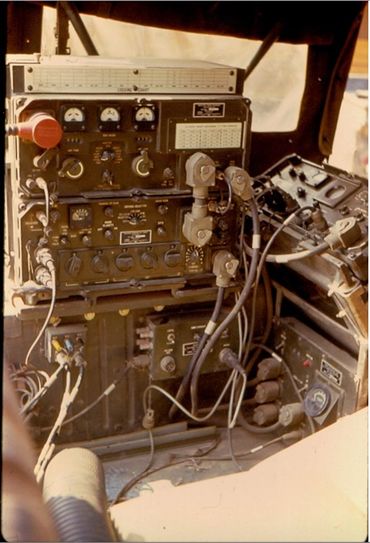
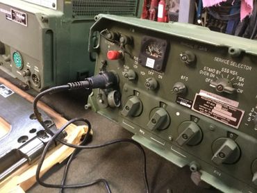
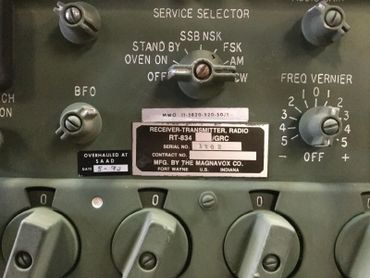
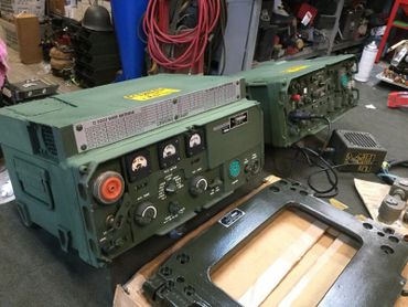
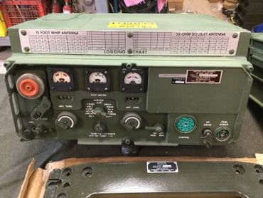
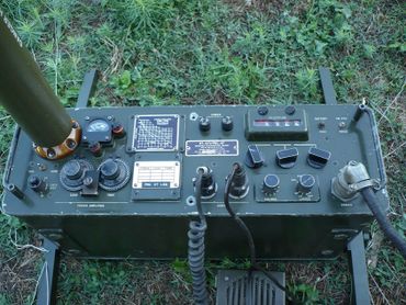
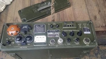
AN/GRC-106
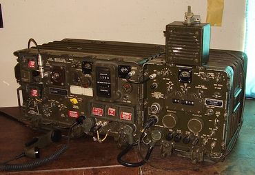
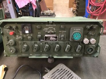
GRC-106 400W SSB Synthesized HF Transmitter - Receiver
The GRC-106 is a Fully Synthesized 400 Watt HF SSB mobile vehicular Receiver / Transmitter Radio Station operating on CW and USB, 28 000 selectively tuned channels spaced in 1 KHz increments in the 2 to 29.999 MHz providing full coverage from 2 to 30Mhz frequency range.
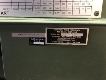
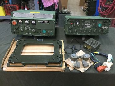
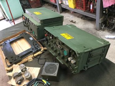
The Radio station consists of two major units that are the Receiver / Transmitter, Radio RT-841/GRC with 100 Hz steps and the HF Amplifier, Radio Frequency AM-3349/GRC 106.
Vernier tuning +/- 500 Hz which allows the receiver section to be continuously tuned over the entire frequency range. The frequency stability is excellent at 5 parts in 10/8 in 24 hours of operation. The Receiver First IF 20 or 30 MHz, Second IF 2.85 Mhz and the Third IF is 1.75 Mhz. Bandwidth is 3.2 KHz which is derived from the crystal filter. Receive sensitivity is less than 0.3 microvolt for 10db signal to noise ratio.
The Transmitters output power is 400w PEP on SSB and compatible AM and 200w average on CW and FSK. Transmitting range is 50 miles with whip antenna and 1000 miles with doublet antenna.
The station operates from 24-28 VDC @ up to 50A in full power transmit mode. The receiver section requires only 1A at 24VDC to operate.
Manuals related to the GRC-106 and installation
TM 11-2300-351-15-1 - Installation of GRC-106 in M151 Series (Not very informative)
TM 11-5820-520-12 - Operator & Organizational Maintenance AN/GRC-106
TM 11-5820-520-20 - Organizational Maintenance AN/GRC-106
TM 11-5820-520-20P-2 - Organizational Maint. & Repair Parts AN/GRC-106A
TM 11-5820-520-34P-2 - Direct Support & General Support, Repair & Special Tools
TM 11-5820-520-34P-3 - Direct Support & General Support, Repair & Special Tools


AN/MRC-107 & 108 Radio Set
This series of radios is very hard to verify what is what. The 107 & 108 are different but similar. They also went through many upgrades over the years. So some of the pictures and references may be confusing. I honestly have a big gap of good understanding with these sets.
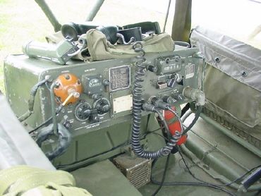
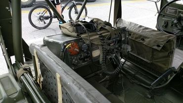
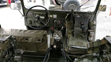
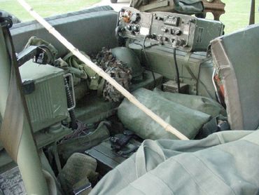
H.F. Transceiver was a AN/MRC-95 by Collins Model Number 618T3, 718F-1 coffin, 313V-1 control head, 618T-3 radio, 426T-1 power inverter, 460D-1 load coil, 670D-1 tuning coil, 76F-3 speaker. The HF Antenna was 32 feet tall mounted with a rubber boot for protection to people passing by so that they would not receive RF Burns. This antenna reduced to 10 sections the width of the jeep. This antenna is a Shakespeare 120 HF Antenna, NSN: 5985-00-846-6442 Military nomenclature: AT-1011/U and is still available from the factory in South Carolina.
UHF Transceiver was a AN/ARC-51BX, 718F-1 coffin, 313V-4 control head, ARC 164 or ARC 51BX radio, 76F-3 speaker. This antenna was shared with the VHF antenna. This antenna was just behind the passengers seat. This antenna was what is called a dual band antenna with VHF in the lower portion and UHF in the upper section. This antenna had separate RF feed lines.
VHF Transceiver was a Collins Model Number 618M, same coffin as UHF, 313V-3 control head, 76F-3 speaker. This radio shared the UHF antenna. This antenna was just behind the passengers seat. This antenna was what is called a dual band antenna with VHF in the lower portion and UHF in the upper section. This antenna had separate RF feed lines.
FM Transceiver was a AN/PRC-25 and a AM-2000 Power Amplifier (RT-254?) This radio had its own antenna about 15 foot long mounted on the left rear corner of the jeep looking from the front to rear.
Secure Voice System AN/KY-38 not found on the MRC-107's which were newer.
Portable Back Packs were a AN/PRC-47 (HF) and AN/PRC-25 (FM) units
The Jeep was a M-151 Military (Ford Motors) Jeep and was modified for this gear including engine, generator, cooling system, and seating. This jeep was very tipsy and could roll over on a dime. You did not get in a hurry in it if you wanted to live!
The Trailer was used to carry our supplies below the Generator which was mounted sideways across the top of the trailer above the Axle for weight control. Spare fuel was found only on the tail end of the trailer, not on the jeep due to high RF fields. Generator Voltage was 115v, AC 400cps


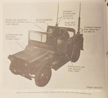
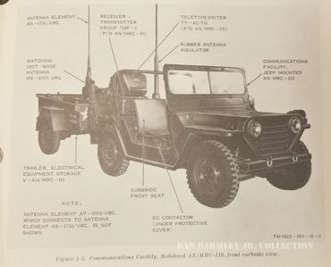
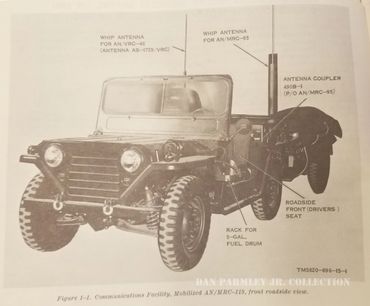
AN/MRC-119 & 120
Additional Information
The AN/MRC-119 & 120 are a combination of truck and trailer.
AN/MRC-120 consists of:
Radio Set AN/MRC-95 Mounted in M151 Series Truck
Radio Set AN/VRC-46 Mounted in M151 Series Truck
All related antenna, cables, mounts and related
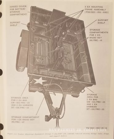
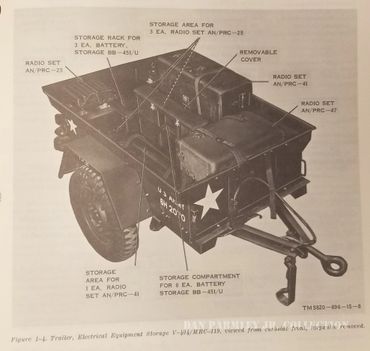
AN/MRC-119 consists of:
Radio Set AN/PRC-25 Mounted in M416 Series Trailer
Radio Set AN/PRC-41 Mounted in M416 Series Trailer
Radio Set AN/PRC-47 Mounted in M416 Series Trailer
All related antenna, cables, mounts and related
TM 11-5820-696-15 - Org. & Dept Maintenance Jeep mounted
TM 11-5820-514-15 - Org. & Dept Maintenance Radio Set AN/MRC-95

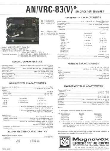
TLQ-17A Radio Set - Amplifier Group OG-181/VRC
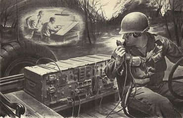
By words John Carroll Military tacticians realize that the ability to receive and transmit information is of critical importance on the battlefield and can mean the difference between victory and defeat. Just as important is eavesdropping and disrupting the enemy’s communications and both sides try to do this; famously, during World War Two, native American Navajo operated as radio operators because the Navajo language was a ‘code’ the Japanese could not break.
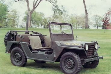
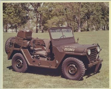
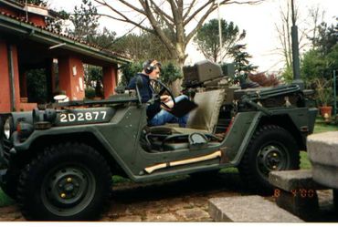
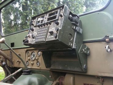
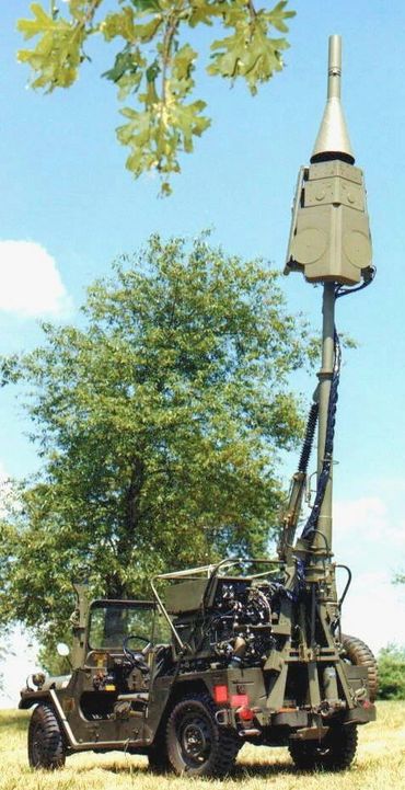
Technological advances and the importance of communications meant that there was rapid growth in the military use of electronics in Brigade And Battalion Intelligence and Electronic Warfare Operations (IEW). Elaborate methods are often employed to deceive or confuse the enemy. Call signs and frequencies can be changed frequently but radio transmitters can be located with the right equipment and enough time. Despite this, battlefield commanders pore over maps monitoring what is happening while people with radios tell them what is going on. To avoid such conversations being listened to by opposing forces additional technology, in the form of radio jammers, was used on the battlefield. One such was the American Electronic Laboratories Inc OG-181/ VRC Piranha Jammer seen here mounted on an M151A2 MUTT.
This jammer was designed to be used by Combat Electronic Warfare Intelligence (CWEI) units and allowed AN/VRC-12 series tactical radio sets to be used as jammers.
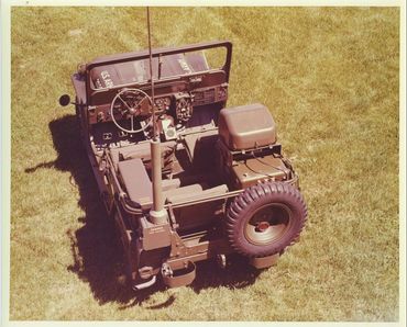
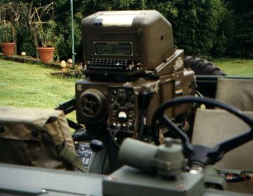
The Piranha system comprised an SG-886 signal generator, a power amplifier, spectrum analyser, frequency scanner, and directional LPA. The directional LPA, mounted on the front bumper of the quarter ton M-151A, is a telescopic hand-cranked antenna which allows the system to be set up in just a few minutes: it can be taken down in seconds and folds back over the vehicle when the team moves. The omni-directional whip antenna on the rear bumper can also be used for VHF COMJAM - communications jam - operations.
The whip antenna also permits jamming operations while on the move - a design feature and capability which is important in fast-paced pursuit operations.
The Truck, Utility, 1/4-Ton, 4×4, M151 was the successor to the Korean War M38 and M38A1 Jeep light utility 4x4. The M151 had an integrated body design which offered a little more space than the previous Jeep models, and featured all-around independent suspension with coil springs. It was subsequently replaced by the larger AM General HMMWV in utility roles in frontline use. With some M151A2 (1968-1988) units still in US military service in 1999, the M151 series achieved a longer run of service than that of the Willys MB/GPW, M38 and M38A1 models combined. Vehicles were used in US actions that included the invasion of Grenada in 1983 where it was reported that communications were difficult because many different units didn’t have each others’ call signs or radio frequency. To compound matters, some were using the same radio frequencies and kept ‘stepping on’ each other’s communications.
Additional Information
AEL Industries, Inc was a premier US electronic defence system manufacturer. It designed and manufactured sophisticated countermeasures, simulation, and radar- warning receiver systems, carried out aircraft engineering, maintenance, and modification services for military and commercial aircraft and provided state-of-the-art antenna, microwave, and integrated circuit components as well as antennas, antenna masts and mounting adapters.
As a US naval officer during World War Two, Leon Riebman was based at the Naval Research Laboratory in Washington, where he developed radar systems. Following this, he returned to the University of Pennsylvania and in 1950 Riebman and two fellow professors - Conrad J Fowler and Robert Goodman - set up American Electronics Laboratories, Inc with Riebman as the president, chief executive officer and director.
His interest in research and development resulted in 10 patents and in 1966 he was named a fellow of the Institute of Electrical and Electronic Engineers.
The company’s name was changed to AEL Industries Inc. in 1976 and American Electronic Laboratories was run as a subsidiary until at least 1985. Following the merger with Tracor in 1996, the company was renamed Tracor AEL. AEL Industries grew until it employed 3,000 people in the US as well as Israel and elsewhere around the world: it was among the first US corporations to develop a subsidiary in Israel. Leon Riebman, electrical engineer and entrepreneur, died on December 20, 2013


AN/PRC-47 Radio Set
Future Information

1.jpg/:/rs=w:370,cg:true,m)
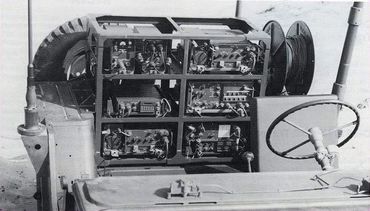
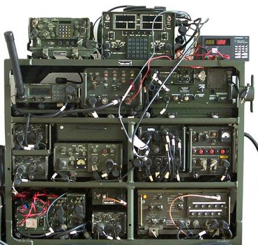
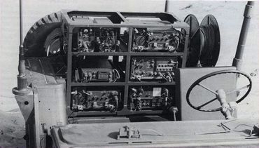
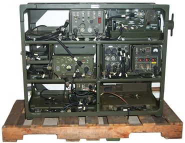
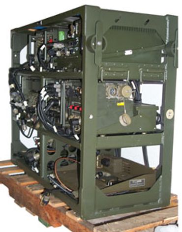
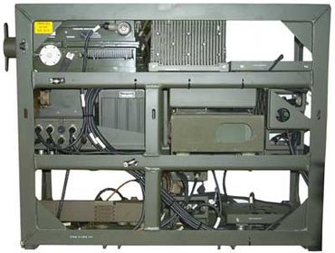
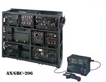
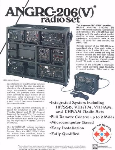
AN/GRC-206
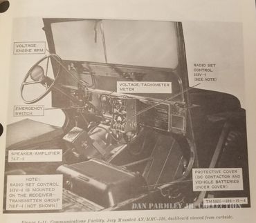
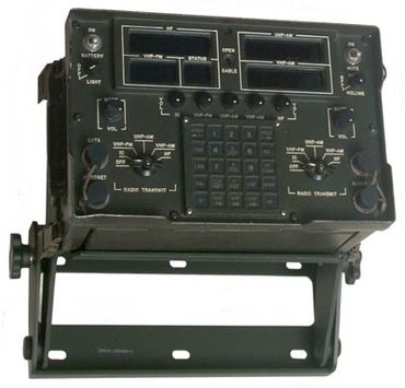
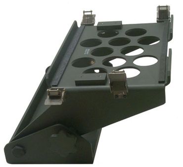
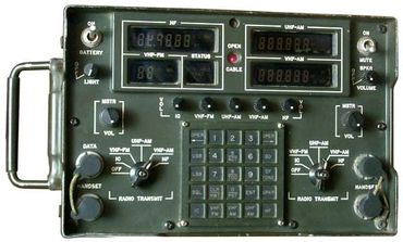
Description & Purpose: The Radio System is a rack mounted tactical communications system. The Radio System is packaged for mounting in the ,M-151Al/A2 (M-151) 1/4 ton utility vehicle, or the M-113-A1/A2 (M-113) Armored Personnel Carrier (APC) When the Radio System is installed in the vehicle (M-151 or M-113) it may be operated as a stationary or mobile communication facility. Both Radio Communication Systems, AN/GRC-206(V)1 (fig. 1-1) and AN/GRC-206(V)2 (fig. 1-2) incorporate HF-SSB, VHF-FM, VHF-AM and UHF-AM subsystems, and associated electronic equipment to provide radio communication capabilities, in three communications bands. Radio Communication System AN/GRC-206(V)1, also provides all the mechanical and electrical interfaces (e.g. equipment mounts, cables, etc. ) necessary to install and operate user supplied communication security (COMSEC) equipment. The Radio System is intended for use by Tactical Air Control Parties for tactical ground-to-ground and ground-to-air communications, and by other Tactical Air Control System (TACS) elements with similar requirements.
ELECTRICAL DESCRIPTION. The Radio System can be operated as a mobile or fixed tactical communication station. Primary power (+22.5 to +30.0 Vdc) for the Radio System is supplied by either of two sources: the vehicle (M-151 or M-113) electrical system during mobile operations; or an auxiliary motor generator (e.g. MEP025) during stationary (fixed) operations. In addition, the Radio System is equipped with a power selector switch which allows the Radio System to be operated from the vehicle batteries for a short time should the main power sources become disabled. The Radio System provides the following communications capabilities: a HFSSB subsystem, operating in the 2.0000 through 29.9999 MHz range; a VHF-FM subsystem, operating in the 30.00 through 75.95 MHz range; a VHF-AM subsystem, operating in the 116.000 through 149.975 MHz range; and a UHF-AM subsystem, operating in the 225.000 through 399.975 MHz range. Separate control and simultaneous operation of the above capabilities is possible, limited only by certain frequency combinations prone to interference, and communication security restrictions. A signal distribution unit (SDU) is used to interface the four subsystems with one or two radio set controls (RSCs) The RSC/SDU interface allows complete control of the Radio System (through the use of local and remote cables) from local or remote locations. Local emergency operation is possible by bypassing (removing system interconnect cables from any subsystem) the RSC/SDU interface, and controlling an individual subsystem by its front panel controls.
The M-151 is a 1/4 ton utility vehicle with a 100-ampero alternator capable of supplying primary power for the Radio System. With minor modifications, the vehicle provides space and facilities to mount the equipment mounting rack, one RSC, and three antennas. It also provides stowage space for optional antennas (and antenna segments) and cables. The M-416 trailer must be used with the M-151 vehicle to stow ancillary items supplied with the Radio System.


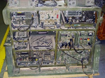

Misc other Radio Sets
This is the section for stuff I can't identify or only have 1 or so pictures of. If you know what something is or any information please share it with me.


%20in%20an%20M151%20jeep.%20The%20718U-2.jpg/:/rs=w:370,cg:true,m)
%20in%20a%20different%20M151%20jeep.%20Th.jpg/:/cr=t:0%25,l:0%25,w:100%25,h:100%25/rs=w:370,cg:true)